
3
Staged Liquid-Liquid Extraction and Hunter Nash Method
$E_n$ = extract leaving stage $n$. This could refer to the mass of the stream or the composition of the stream.
$F$ = solvent entering extractor stage 1. This could refer to the mass of the stream or the composition of the stream.
$n$ = generic stage number
$N$ = Final stage. This is where the fresh solvent S enters the system and the final raffinate $R_N$ leaves the system.
$M$ = Composition of the mixture representing the overall system. Points ($F$ and $S$) and ($E_1$ and $R_N$) must be connected by a straight line that passes through point $M$. $M$ will be located within the ternary phase diagram.
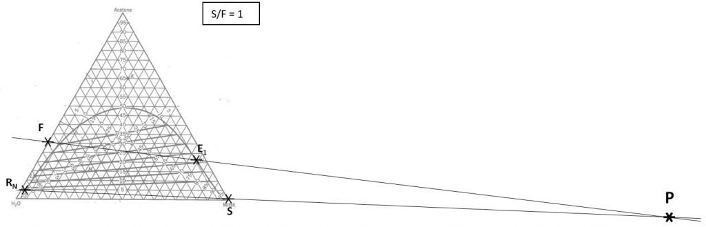
$P$ = Operating point. $P$ is determined by the intersection of the straight line connecting points ($F$, $E_1$) and the straight line connecting points ($S$, $R_N$). Every pair of passing streams must be connected by a straight line that passes through point $P$. $P$ is expected to be located outside of the ternary phase diagram.
$R_n$ = raffinate leaving stage $n$. This could refer to the mass of the stream or the composition of the stream.
$S$ = solvent entering extractor stage $N$. This could refer to the mass of the stream or the composition of the stream.
$S/F$ = mass ratio of solvent to feed
$(x_i)_n$ = Mass fraction of species $i$ in the raffinate leaving stage $n$
$(y_i)_n$ = Mass fraction of species $i$ in the extract leaving stage $n$
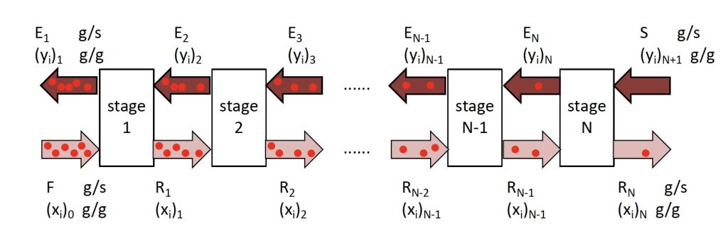
Determining number of stages $N$ when (1) feed rate; (2) feed composition; (3) incoming solvent rate; (4) incoming solvent composition; and (5) outgoing raffinate composition have been specified/selected.
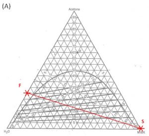
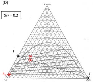
- Locate points $F$ and $S$ on the ternary phase diagram. Connect with a straight line.
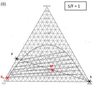
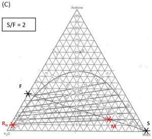
- Do a material balance to find the composition of one species in the overall mixture. Use this composition to locate point $M$ along the straight line connection points $F$ and $S$. Note the position of point $M$.
- Locate point $R_N$ on the ternary phase diagram. It will be on the equilibrium curve. Draw a straight line from $R_N$ to $M$ and extend to find the location of $E_1$ on the equilibrium curve.
- On a fresh copy of the graph, with plenty of blank space on each side of the diagram, note the location of points $F$, $S$, and $R_N$ (specified/selected) and $E_1$ (determined in step 3).
- Draw a straight line between $F$ and $E_1$. Extend to both sides of the diagram. Draw a second straight line between $S$ and $R_N$. Note the intersection of these two lines and label as “$P$”.
- Determine the number of equilibrium stages required to achieve the desired separation with the selected solvent mass.
– Stream $R_N$ is in equilibrium with stream $E_N$. Follow the tie-lines from point $R_N$ to $E_N$.
– Stream $E_N$ passes stream $R_{N-1}$. Connect point $E_N$ to operating point $P$ with a straight line, mark the location of $R_{N-1}$.
– Stream $R_{N-1}$ is in equilibrium with stream $E_{N-1}$. Follow the tie-lines from stream $R_{N-1}$ to $E_{N-1}$.
– Stream $E_{N-1}$ passes stream $R_{N-2}$. Connect $E_{N-1}$ to operating point $P$ with a straight line, mark the location of $R_{N-2}$.
– Continue in this manner until the extract composition has reached or passed $E_{1}$. Count the number of equilibrium stages.
Watch this two-part series of videos from LearnChemE that shows how to use the Hunter Nash method to find the number of equilibrium stages required for a liquid-liquid extraction process.
- Hunter Nash Method 1: Mixing and Operating Points (9:30)
- Hunter Nash Method 2: Number of Stages (6:30)
1000 kg/hr of a feed containing 30 wt% acetone, 70 wt% water. The solvent is pure MIBK. We intend that the raffinate contain no more than 5.0 wt% acetone. How many stages will be required for each proposed solvent to feed ratio in the table below?
| $\bold{S/F}$ | $\bold{S}$ (kg/hr) | $\bold{(x_A)_M}$ | target $\bold{(y_A)_1}$ | $\bold{N}$ |
| 1.0 | ||||
| 2.0 | ||||
| 0.2 |
Hunter Nash Method for Finding Smin, Tank Sizing and Power Consumption for Mixer-Settler Units
Staged LLE: Hunter-Nash Method for Finding the Minimum Solvent to Feed Ratio
$E_n$ = extract leaving stage $n$. This could refer to the mass of the stream or the composition of the stream.
$F$ = solvent entering extractor stage 1. This could refer to the mass of the stream or the composition of the stream.
$n$ = generic stage number
$N$ = Final stage. This is where the fresh solvent $S$ enters the system and the final raffinate $R_N$ leaves the system.
$M$ = Composition of the overall mixture. Points ($F$ and $S$) and ($E_1$ and $R_N$) are connected by a straight line passing through $M$.
$P$ = Operating point. Every pair of passing streams must be connected by a straight line that passes through $P$.
$R_n$ = raffinate leaving stage $n$. This could refer to the mass of the stream or the composition of the stream.
$S$ = solvent entering extractor stage $N$. This could refer to the mass of the stream or the composition of the stream.
$S/F$ = mass ratio of solvent to feed
$S_{\rm min}/F$ = Minimum feasible mass ratio to achieve the desired separation, assuming the use of an infinite number of stages.
$(x_i)_n$ = Mass fraction of species $i$ in the raffinate leaving stage $n$
$(y_i)_n$ = Mass fraction of species $i$ in the extract leaving stage $n$
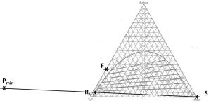
$P_{\rm min}$ = Point associated with the minimum feasible $S/F$ for this feed, solvent and (raffinate or extract) composition. $P_{\rm min}$ is the intersection of the line connecting points ($R_N$, $S$) and the line that is an extension of the upper-most equilibrium tie-line.
Determining minimum feasible solvent mass ratio ($S_{\rm min}/F$) when (1) feed composition; (2) incoming solvent composition; and (3) outgoing raffinate composition have been specified/selected.
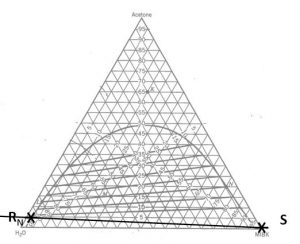
- Locate points $S$ and $R_N$ on the phase diagram. Connect with a straight line.
- Extend the upper-most tie-line in a line that connects with the line connecting points ($S$ and $R_N$). Label the intersection $P_{\rm min}$.
- Find point $F$ on the diagram. Draw a line from $P_{\rm min}$ to F and extend to the other side of the equilibrium curve. Label $E_1$@$S_{\rm min}$.
- On a fresh copy of the phase diagram, label points $F$, $S$, $R_N$ and $E_1$@$S_{\rm min}$. Draw one line connecting points $S$ and $F$ and another line connecting points $E_1$@$S_{\rm min}$
- and $R_N$. The intersection of these two lines is mixing point $M$. Note the composition of species $i$ at this location.
- Calculate
\begin{displaymath}
\tag{5.1}
\frac{S_{\rm min}}{F}=\frac{(x_i)_F-(x_i)_M}{(x_i)_M-(x_i)_S}
\end{displaymath}
We have a 1000 kg/hr feed that contains 30 wt% acetone and 70 wt% water. We want our raffinate to contain no more than 5.0 wt% acetone. What is the minimum mass of pure MIBK required?
Liquid-Liquid Extraction: Sizing Mixer-settler Units
$\Phi_C$ = volume fraction occupied by the continuous phase
$\Phi_D$ = volume fraction occupied by the dispersed phase
$\mu_C$ = viscosity of the continuous phase (mass time-1 length-1)
$\mu_D$ = viscosity of the dispersed phase (mass time-1 length-1)
$\mu_M$ = viscosity of the mixture (mass time-1 length-1)
$\rho_C$ = density of the continuous phase (mass volume-1)
$\rho_D$ = density of the dispersed phase (mass volume-1)
$\rho_M$ = average density of the mixture (mass volume-1)
$D_i$ = impeller diameter (length)
$D_T$ = vessel diameter (length)
$H$ = total height of mixer unit (length)
$N$ = rate of impeller rotation (time-1)
$N_{\rm Po}$ = impeller power number, read from Fig 8-36 or Perry’s 15-54 (below) based on value of $N_{Re}$ (unitless)
$(N_{\rm Re})_C$ = Reynold’s number in the continuous phase = inertial force/viscous force (unitless)
$P$ = agitator power (energy time-1)
$Q_C$ = volumetric flowrate, continuous phase (volume time-1)
$Q_D$ = volumetric flowrate, dispersed phase (volume time-1)
$V$ = vessel volume (volume)
Tank and impeller sizing
\begin{displaymath}
\tag{5.2}
{\rm residence\; time} = \frac{V}{Q_C+Q_D}
\end{displaymath}
Geometry of a cylinder
\begin{displaymath}
\tag{5.3}
V = \frac{{\pi}D_T^2H}{4}
\end{displaymath}
General guidelines
\begin{displaymath}
\tag{5.4}
\frac{H}{D_T}=1
\end{displaymath}
\begin{displaymath}
\tag{5.5}
\frac{D_i}{D_T}=\frac{1}{3}
\end{displaymath}
Impeller power consumption:
\begin{equation}
\tag{5.6}
P=N_{Po}N^3D_i^5{\rho}_m
\end{equation}
\begin{equation}
\tag{5.7}
N_{Re}=\frac{D_i^2N{\rho}_M}{{\mu}_M}
\end{equation}
\begin{equation}
\tag{5.8}
{\rho}_M={\rho}_C{\Phi}_C+{\rho}_D{\Phi}_D
\end{equation}
\begin{equation}
\tag{5.9}
{\mu}_M=\frac{{\mu}_C}{{\Phi}_C}\left[1+\frac{1.5{\mu}_D{\Phi}_D}{{\mu}_C+{\mu}_D}\right]
\end{equation}
Modeling Mass Transfer in Mixer-Settler Units
$\Delta\rho$ = density difference (absolute value) between the continuous and dispersed phases (mass volume-1)
$\phi_C$ = volume fraction occupied by the continuous phase
$\phi_D$ = volume fraction occupied by the dispersed phase
$\mu_C$ = viscosity of the continuous phase (mass time-1 length-1)
$\mu_D$ = viscosity of the dispersed phase (mass time-1 length-1)
$\mu_M$ = viscosity of the mixture (mass time-1 length-1)
$\rho_C$ = density of the continuous phase (mass volume-1)
$\rho_D$ = density of the dispersed phase (mass volume-1)
$\rho_M$ = average density of the mixture (mass volume-1)
$\sigma$ = interfacial tension between the continuous and dispersed phases
(mass time-2)
$a$ = interfacial area between the two phases per unit volume (area volume-1)
$c_{D,\rm in}$, $c_{D,\rm out}$ = concentration of solute in the incoming or outgoing dispersed streams (mass volume-1)
$c^*_D$ = concentration of solute in the dispersed phase if in equilibrium with the outgoing continuous phase (mass volume-1)
$D_C$ = diffusivity of the solute in the continuous phase (area time-1)
$D_D$ = diffusivity of the solute in the dispersed phase (area time-1)
$D_i$ = impeller diameter (length)
$D_T$ = vessel diameter (length)
$d_{vs}$ = Sauter mean droplet diameter; actual drop size expected to range from $0.3d_{vs}-3.0d_{vs}$ (length)
$E_{MD}$ = Murphree dispersed-phase efficiency for extraction
$g$ = gravitational constant (length time-2)
$H$ = total height of mixer unit (length)
$k_c$ = mass transfer coefficient of the solute in the continuous phase (length time-1)
$k_D$ = mass transfer coefficient of the solute in the dispersed phase (length time-1)
$K_{OD}$ = overall mass transfer coefficient, given on the basis of the dispersed phase (length time-1)
$m$ = distribution coefficient of the solute, $\Delta c_C/\Delta c_D$ (unitless)
$N$ = rate of impeller rotation (time-1)
$(N_{\rm Eo})_C$ = Eotvos number = gravitational force/surface tension force (unitless)
$(N_{\rm Fr})_C$ = Froude number in the continuous phase = inertial force/gravitational force (unitless)
$N_{\rm min}$ = minimum impeller rotation rate required for complete dispersion of one liquid into another
$(N_{\rm Re})_C$ = Reynold’s number in the continuous phase = inertial force/viscous force (unitless)
$(N_{\rm Sh})_C$ = Sherwood number in the continuous phase = mass transfer rate/diffusion rate (unitless)
$(N_{\rm Sc})_C$ = Schmidt number in the continuous phase = momentum/mass diffusivity (unitless)
$(N_{\rm We})_C$ = Weber number = inertial force/surface tension (unitless)
$Q_D$ = volumetric flowrate of the dispersed phase (volume time-1)
$V$ = vessel volume (volume)
Calculating $N_{\rm min}$
\begin{equation}
\tag{6.1}
\frac{N_{\rm min}^2{\rho}_MD_i}{g{\Delta}{\rho}}=1.03\left(\frac{D_T}{D_i}\right)^{2.76}({\phi}_D)^{0.106}\left(\frac{{\mu}_M^2{\sigma}}{D_i^5{\rho}_Mg^2({\Delta}{\rho})^2}\right)^{0.084}
\end{equation}
\begin{equation}
\tag{6.2}
{\rho}_M={\rho}_C{\phi}_C+{\rho}_D{\phi}_D
\end{equation}
\begin{equation}
\tag{6.3}
{\mu}_M=\frac{{\mu}_C}{{\phi}_C}\left(1+\frac{1.5{\mu}_D{\phi}_D}{{\mu}_C+{\mu}_D}\right)
\end{equation}
Estimating Murphree efficiency for a proposed design
Sauter mean diameter
\begin{equation}
\tag{6.4}
{\rm if}\;\; N_{\rm We} < 10,000,\; d_{vs}=0.052D_i(N_{\rm We})^{-0.6}\exp({4{\phi}_D})
\end{equation}
\begin{equation}
\tag{6.5}
{\rm if}\;\; N_{\rm We} >10,000,\; d_{vs}=0.39D_i(N_{\rm We})^{-0.6}
\end{equation}
\begin{equation}
\tag{6.6}
N_{\rm We}=\frac{D_i^3N^2{\rho}_C}{\sigma}
\end{equation}
mass transfer coefficient of the solute in each phase
\begin{equation}
\tag{6.7}
k_D=\frac{6.6D_D}{d_{vs}}
\end{equation}
\begin{equation}
\tag{6.8}
k_C=\frac{(N_{\rm Sh})_CD_c}{d_{vs}}
\end{equation}
\begin{align}
\tag{6.9}
& (N_{\rm Sh})_C = 1.237\times 10^{-5}(N_{\rm Sc})_C^{1/3}(N_{\rm Re})_C^{2/3}(\phi_D)^{-1/2}\\
& (N_{\rm Fr})_C^{5/12}\left(\frac{D_i}{d_{vs}}\right)^2
\left(\frac{d_{vs}}{D_T}\right)^{1/2}(N_{\rm Eo})_C^{5/4}
\end{align}
\begin{equation}
\tag{6.10}
(N_{\rm Sc})_C=\frac{{\mu}_C}{{\rho}_CD_C}
\end{equation}
\begin{equation}
\tag{6.11}
(N_{\rm Re})_C=\frac{D_i^2N{\rho}_C}{{\mu}_C}
\end{equation}
\begin{displaymath}
\tag{6.12}
(N_{\rm Fr})_C=\frac{D_iN^2}{g}
\end{displaymath}
\begin{equation}
\tag{6.13}
(N_{\rm Eo})_C=\frac{{\rho}_Dd_{vs}^2g}{{\sigma}}
\end{equation}
Overall mass transfer coefficient for the solute
\begin{equation}
\tag{6.14}
\frac{1}{K_{OD}}=\frac{1}{k_D}+\frac{1}{mk_C}
\end{equation}
Murphree efficiency
\begin{equation}
\tag{6.15}
E_{MD}=\frac{K_{OD}aV}{Q_D}\left(1+{\frac{K_{OD}aV}{Q_D}}\right)^{-1}
\end{equation}
\begin{equation}
\tag{6.16}
a=\frac{6\phi_D}{d_{vs}}
\end{equation}
Experimental assessment of efficiency
\begin{equation}
\tag{6.17}
E_{MD}=\frac{c_{D,\rm in}-c_{D,\rm out}}{c_{D,\rm in}-c^*_D}
\end{equation}
1000 kg/hr of 30 wt% acetone and 70 wt% water is to be extracted with 1000 kg/hr of pure MIBK. Assume that the extract is the continuous phase, a residence time of 5 minutes in the mixing vessel, standard sizing of the mixing vessel and impeller. Find the power consumption and Murphree efficiency if the system operates at $N_{\rm min}$, controlled at the level of 1 rev/s. Ignore the contribution of the solute and the co-solvent to the physical properties of each phase.
- MIBK
- density = 802 kg m-3
- viscosity = 0.58 cP
- diffusivity with acetone at 25°C = 2.90×10⁻⁹ m2 s-1
- Water
- density = 1000 kg m-3
- viscosity = 0.895 cP
- diffusivity with acetone at 25°C = 1.16×10⁻⁹ m2 s-1
- The interfacial tension of water and MIBK at 25°C = 0.0157 kg s-2. Use the ternary phase diagram to find $m$.
Liquid-Liquid Extraction Columns
$\Delta \rho$ = density difference (absolute value) between the continuous and dispersed phases (mass volume-1)
$\mu_C$ = viscosity of the continuous phase (mass time-1 length-1)
$\rho_C$ = density of the continuous phase (mass volume-1)
$\rho_D$ = density of the dispersed phase (mass volume-1)
$\sigma$ = interfacial tension between the continuous and dispersed phases
(mass time-2)
$D_T$ = column diameter (length)
$H$ = total height of column (length)
${\rm HETS}$ = height of equilibrium transfer stage (length)
$m^*_C$ = mass flowrate of the entering continuous phase (mass time-1)
$m^*_D$ = mass flowrate of the entering dispersed phase (mass time-1)
$N$ = required number of equilibrium stages
$u_0$ = characteristic rise velocity of a droplet of the dispersed phase (length time-1)
$U_i$ = superficial velocity of phase $i$ (C = continuous, downward; D = dispersed, upward) (length time-1)
$V^*_i$ = volumetric flowrate of phase $i$ (volume time-1)
\begin{displaymath}
\tag{7.1}
U_i=\frac{4V^*_i}{{\pi}D_T^2}
\end{displaymath}
definition of superficial velocity
\begin{displaymath}
\tag{7.2}
\frac{U_D}{U_C}=\frac{m^*_D}{m^*_C}\left(\frac{{\rho}_C}{\rho_D}\right)
\end{displaymath}
\begin{displaymath}
\tag{7.3}
(U_D+U_C)_{\rm actual}=0.50(U_D+U_C)_f
\end{displaymath}
for operation at 50% of flooding
\begin{displaymath}
\tag{7.4}
u_0=\frac{0.01{\sigma}{\Delta}{\rho}}{{\mu}_C{\rho}_C}
\end{displaymath}
for rotating-disk columns, $D_T$ = 8 to 42 inches, with one aqueous phase
\begin{displaymath}
\tag{7.5}
D_T=\left(\frac{4m^*_D}{{\rho}_DU_D{\pi}}\right)^{0.5}=\left(\frac{4m^*_C}{{\rho}_CU_C{\pi}}\right)^{0.5}
\end{displaymath}
\begin{displaymath}
\tag{7.6}
H = {\rm HETS}*N
\end{displaymath}
1000 kg/hr of 30 wt% acetone and 70 wt% water is to be extracted with 1000 kg/hr of pure MIBK in a 2-stage column process. Assume that the extract is the dispersed phase. Ignoring the contribution of the solute and the co-solvent to the physical properties of each phase, find the required column diameter and height.
- MIBK
- density = 802 kg m-3
- viscosity = 0.58 cP
- Water
- density = 1000 kg m-3
- viscosity = 0.895 cP
- The interfacial tension of water and MIBK at 25°C = 0.0157 kg s-2.